
ダイアグラムとテキストの備忘録です。
ベース(T811)
T811 等加速度運動のモデルを使って、ダイアグラムとテキストの内容を確認します。(ビュー(v1.19.0))

モデル
設置したコンポーネントと接続関係をみます。
model T811_Sign_convection_koubun ←①モデル(ファイル)
  Modelica.Blocks.Sources.Constant const(k = 1)  ←②コンポーネント
  annotation(
    Placement(visible = true, transformation(origin = {-36, 0}, extent = {{-10, -10}, {10, 10}}, rotation = 0))); ←③位置・サイズ表記
  Modelica.Mechanics.Translational.Sources.Force force ←②コンポーネント
  annotation(
    Placement(visible = true, transformation(origin = {6, 0}, extent = {{-10, -10}, {10, 10}}, rotation = 0))); ←③位置・サイズ表記
  Modelica.Mechanics.Translational.Components.Mass mass(L = 1, m = 1, s(fixed = true), v(fixed = true))  ←②コンポーネント
  annotation(
    Placement(visible = true, transformation(origin = {46, 0}, extent = {{-10, -10}, {10, 10}}, rotation = 0))); ←③位置・サイズ表記
equation ←④関係式
  connect(const.y, force.f) ←⑤接続
  annotation(
    Line(points = {{-25, 0}, {-7, 0}}, color = {0, 0, 127})); ←③_2 接続位置
  connect(force.flange, mass.flange_a) ←⑤接続(flangeとflangeの接続)
 annotation(
    Line(points = {{16, 0}, {36, 0}}, color = {0, 127, 0})); ←③_2 接続位置
  annotation( ←⑥ モデルの情報記載
    uses(Modelica(version = "4.0.0")),
    Documentation(info = "<html><head></head><body><p>確認用実施</p></body></html>"),
  Diagram(graphics = {Text(origin = {-43, 22}, extent = {{-21, 4}, {21, -4}}, textString = "信号で1を一定値で入力")}));
end T811_Sign_convection_koubun; ←①モデル(ファイル)の終わり
①モデル(ファイル)
モデルの定義。
②コンポーネント
設定したコンポーネントのパスと引数がある場合には記述されます。
③位置・サイズ表記(annotation)
コンポーネントの位置とサイズを表示しています。
④関係式
コンポーネントを設置したモデルファイルではコンポーネント間の接続情報になります。
⑤接続(connect)
関係付けられたコンポーネント情報になります。
ConstantをMassに直接つなげませんが、Forceのflangeを介して接続します。
③_2 接続位置
接続ラインの情報(位置)が表記されます。
コンポーネント
使用される引数(パラメータ)と関係式(equation)をみます。
const
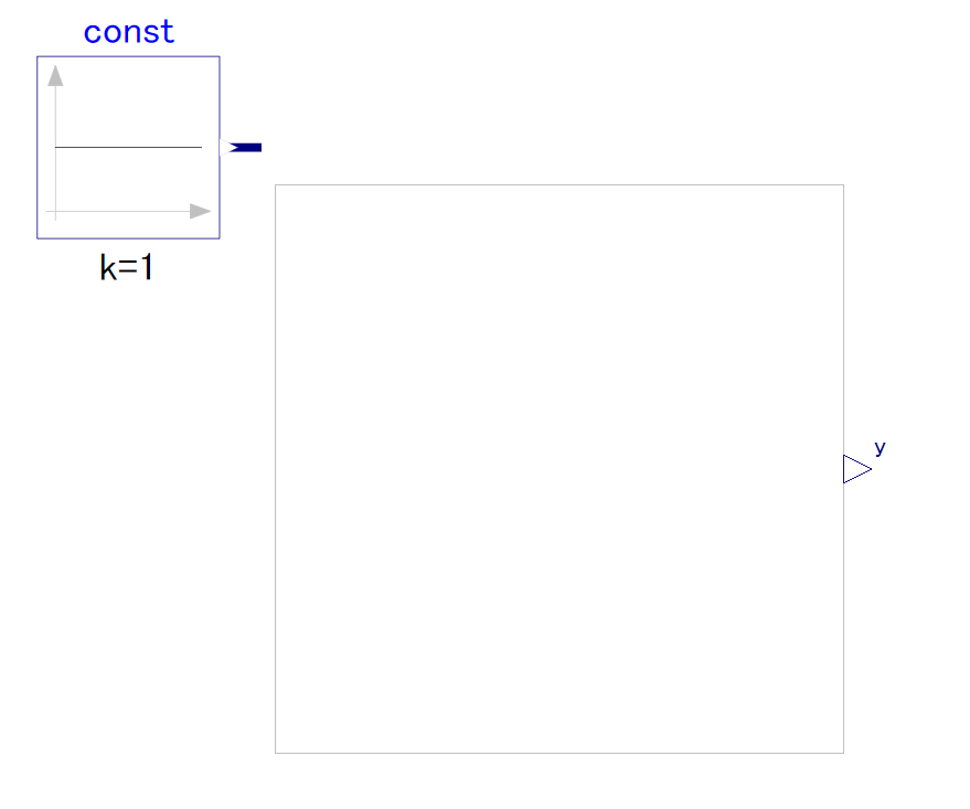
出力のY端子があります。
block Constant "Generate constant signal of type Real"
  parameter Real k(start=1) "Constant output value"
  annotation(Dialog(groupImage="modelica://Modelica/Resources/Images/Blocks/Sources/Constant.png"));
  extends Interfaces.SO;

equation
  y = k;
  annotation (
    defaultComponentName="const",
    Icon(coordinateSystem(
        preserveAspectRatio=true,
        extent={{-100,-100},{100,100}}), graphics={
        Line(points={{-80,68},{-80,-80}}, color={192,192,192}),
        Polygon(
          points={{-80,90},{-88,68},{-72,68},{-80,90}},
          lineColor={192,192,192},
          fillColor={192,192,192},
          fillPattern=FillPattern.Solid),
        Line(points={{-90,-70},{82,-70}}, color={192,192,192}),
        Polygon(
          points={{90,-70},{68,-62},{68,-78},{90,-70}},
          lineColor={192,192,192},
          fillColor={192,192,192},
          fillPattern=FillPattern.Solid),
        Line(points={{-80,0},{80,0}}),
        Text(
          extent={{-150,-150},{150,-110}},
          textString="k=%k")}),
    Documentation(info="<html>
<p>
The Real output y is a constant signal:
</p>

<p>
<img src=\"modelica://Modelica/Resources/Images/Blocks/Sources/Constant.png\"
   alt=\"Constant.png\">
</p>
</html>"));
end Constant;
force
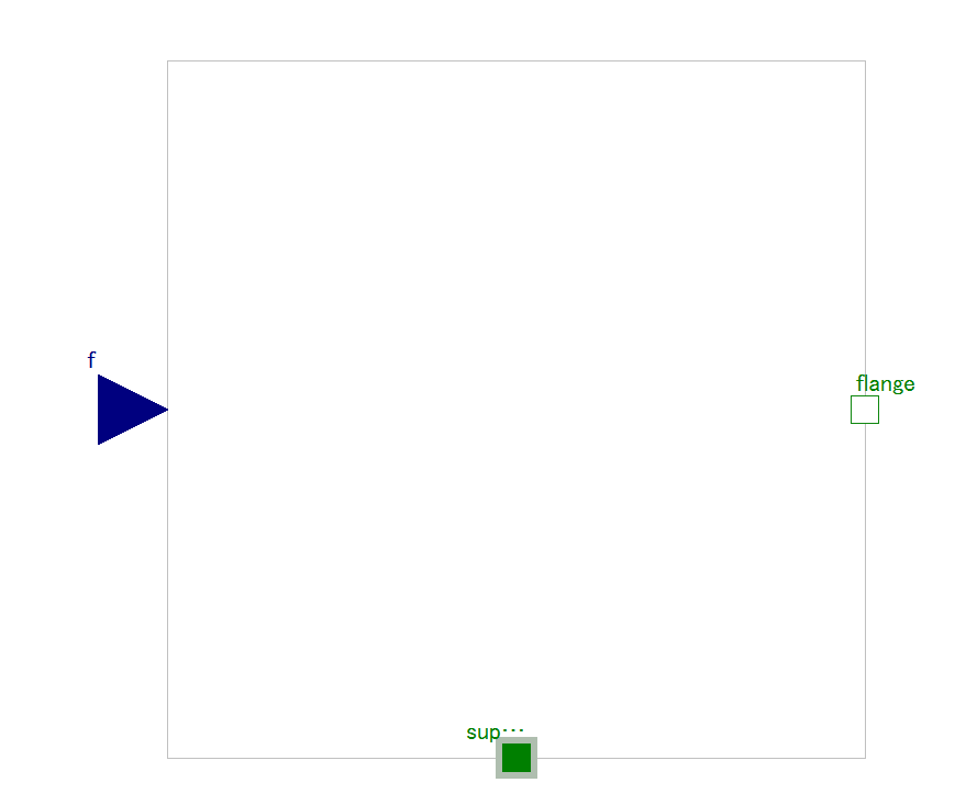
入力端子:f
出力点:frange
within Modelica.Mechanics.Translational.Sources;
model Force
  "External force acting on a drive train element as input signal"
  extends Modelica.Mechanics.Translational.Interfaces.PartialElementaryOneFlangeAndSupport2;
  Modelica.Blocks.Interfaces.RealInput f(unit="N")
    "Driving force as input signal" annotation (Placement(transformation(
          extent={{-140,-20},{-100,20}})));

equation
  flange.f = -f;

  annotation (
    Documentation(info="<html>
<p>
The input signal \"f\" in [N] characterizes an <em>external
force</em> which acts (with positive sign) at a flange,
i.e., the component connected to the flange is driven by force f.
</p>
<p>
Input signal f can be provided from one of the signal generator
blocks of Modelica.Blocks.Source.
</p>
</html>"),
    Icon(
      coordinateSystem(
        preserveAspectRatio=true,
        extent={{-100,-100},{100,100}}),
      graphics={
        Line(points={{0,-60},{0,-101}}, color={0,127,0}),
        Polygon(
          points={{-100,10},{20,10},{20,41},{90,0},{20,-41},{20,-10},{-100,-10},{-100,10}},
          lineColor={0,127,0},
          fillColor={160,215,160},
          fillPattern=FillPattern.Solid),
        Text(
          extent={{-150,-32},{-80,-62}},
          textString="f"),
        Text(
          extent={{-150,90},{150,50}},
          textString="%name",
          textColor={0,0,255}),
        Polygon(
          points={{50,-54},{-30,-54},{-30,-46},{-60,-60},{-30,-74},{-30,-66},{50,-66},{50,-54}},
          lineColor={0,127,0},
          fillColor={160,215,160},
          fillPattern=FillPattern.Solid)}));
end Force;
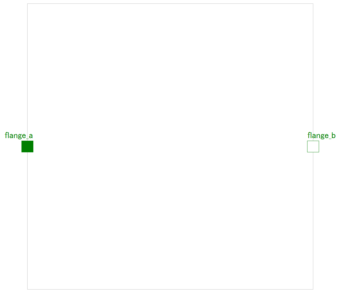
mass
within Modelica.Mechanics.Translational.Components;
model Mass "Sliding mass with inertia"
  parameter SI.Mass m(min=0, start=1) "Mass of the sliding mass";
  parameter StateSelect stateSelect=StateSelect.default
    "Priority to use s and v as states" annotation (Dialog(tab="Advanced"));
  extends Translational.Interfaces.PartialRigid(L=0,s(start=0, stateSelect=
          stateSelect));
  SI.Velocity v(start=0, stateSelect=stateSelect)
    "Absolute velocity of component";
  SI.Acceleration a(start=0) "Absolute acceleration of component";

equation
  v = der(s);
  a = der(v);
  m*a = flange_a.f + flange_b.f;
  annotation (
    Documentation(info="<html>
<p>
Sliding mass with <em>inertia, without friction</em> and two rigidly connected flanges.
</p>
<p>
The sliding mass has the length L, the position coordinate s is in the middle.
Sign convention: A positive force at flange flange_a moves the sliding mass in the positive direction.
A negative force at flange flange_a moves the sliding mass to the negative direction.
</p>

</html>"),
    Icon(coordinateSystem(preserveAspectRatio=true, extent={{-100,-100},{
            100,100}}), graphics={
        Line(points={{-100,0},{100,0}}, color={0,127,0}),
        Rectangle(
          extent={{-55,-30},{56,30}},
          fillPattern=FillPattern.Sphere,
          fillColor={160,215,160},
          lineColor={0,127,0}),
        Polygon(
          points={{50,-90},{20,-80},{20,-100},{50,-90}},
          lineColor={95,127,95},
          fillColor={95,127,95},
          fillPattern=FillPattern.Solid),
        Line(points={{-60,-90},{20,-90}}, color={95,127,95}),
        Text(
          extent={{-150,85},{150,45}},
          textString="%name",
          textColor={0,0,255},
          fillColor={110,210,110},
          fillPattern=FillPattern.Solid),
        Text(
          extent={{-150,-45},{150,-75}},
          textString="m=%m",
          fillColor={110,221,110},
          fillPattern=FillPattern.Solid,
          fontSize=0)}));
end Mass;
der()は微分
コメント